Here is the fun part about ESP32 boards: you can plug a glowing LED filament, a rainbow strip or a tiny screen into four little wires and have it working in an afternoon, with no soldering and no electronics background. The very first build needs no code at all: plug two wires in and it glows. From there, five beginner builds go from a single blinking LED to a NeoPixel strip and an OLED display, each with a wiring diagram and short code that compiles for the Cardputer ADV. We use the Cardputer ADV's Grove port as the worked example, and every build works on any ESP32 once you change the pin number.
The short answer
Easiest of all: a COB LED filament rated for 5V lights straight from a board's 5V and GND, no code needed. Beyond that, an ESP32 pin gives out 3.3V and a little current, so: a single LED needs a resistor (150 Ω for red), dimming uses the ESP32's LEDC PWM hardware, and anything hungrier (a filament you want to dim, a WS2812 strip) takes its power from 5V, with the pin only switching it or sending one data wire. Keep strips to 8 to 16 LEDs on a small board's 5V and cap them in FastLED. An I2C OLED needs just two data pins and the U8g2 library.
- What you need
- Build 0: Light a filament with zero code
- Three rules that keep your board alive
- How to upload a sketch
- Project 1: Blink an LED
- Project 2: Fade it with PWM (ESP32 LEDC)
- Project 3: Glow an LED filament
- Project 4: ESP32 LED strip (WS2812 NeoPixels)
- Project 5: ESP32 OLED display
- No code at all: UIFlow2 blocks
- Troubleshooting
- Make music on the same board
- ESP32 LED FAQ
What you need
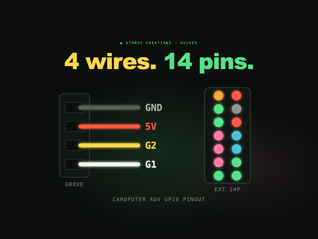
Any ESP32 board works. Ours is the M5Stack Cardputer ADV, an ESP32-S3 with a keyboard, screen and battery built in, so there is nothing to wire up except the project itself. Its Grove port (the little 4-pin socket) carries everything these builds need. These are the only four wires you will touch:
| Grove wire | Cardputer | On another ESP32 board |
|---|---|---|
| Yellow | GPIO2 (I2C SDA) | Any free GPIO |
| White | GPIO1 (I2C SCL) | Any free GPIO |
| Red | 5V power | The 5V pin, if your board has one |
| Black | GND | GND |
The original Cardputer uses the same two Grove pins. For every other pin on the board, see our Cardputer GPIO pinout guide. New to microcontrollers? ESP32 vs Raspberry Pi explains why an ESP32 is the right tool for LEDs.
| Part | For | Notes |
|---|---|---|
| Grove to Dupont cable | All | Turns the Grove plug into breadboard jumpers (M5Stack's is 20 cm) |
| Breadboard + jumpers | All | Any small one |
| 5V COB LED filament | 0 | The listing must say 5V |
| Red 5mm LEDs | 1, 2 | Red, not white (see Project 1) |
| Resistors | All | 150 Ω, 220 Ω, 330 Ω, 47 Ω, 100 Ω, 100 kΩ (a ¼ W kit covers them) |
| Adafruit nOOds 3V filament | 3 | Flexible LED filament, any colour |
| AO3400A MOSFET on a breakout | 3 | Tiny SMD part, so get it on a breadboard-friendly board |
| 8-LED WS2812B stick | 4 | Plus a 1000 µF, 6.3V or higher capacitor |
| SSD1306 128×64 I2C OLED | 5 | The common 4-pin kind |
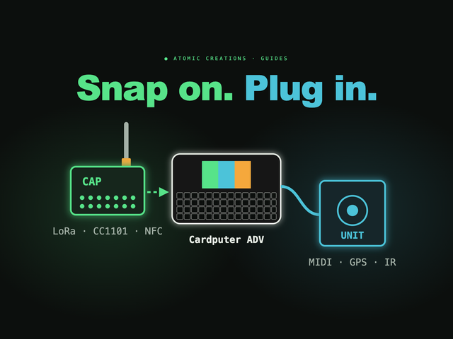
Rather not use a breadboard at all? M5Stack's Unit RGB (3 LEDs), Unit NeoHEX (37 LEDs) and Unit OLED plug straight into the Grove port. Our Cardputer ADV accessories guide covers what else fits.
Build 0: Light a filament with zero code
This is the one that makes people grin. Take a COB LED filament sold as a 5V part, connect its + end to the red Grove wire and its − end to the black one, and switch the Cardputer on. It glows. No resistor, no sketch, nothing to upload. We tried it on our own Cardputer ADV and it lit right up.
- Why it works: a filament sold for 5V is made to run straight from 5V, so the current limiting is already taken care of. Check the listing says 5V before you plug it in, and check its current draw fits the budget in Project 4.
- A 3V filament is different. Adafruit's nOOds, for example, are rated for 3V at 50 mA max. Wired straight to 5V they are overdriven: they run hot and die early. Those need the resistor or MOSFET wiring in Project 3.
- Want to dim it, blink it or fade it from code? That is the MOSFET build in Project 3, the natural next step.
Three rules that keep your board alive
- Pins are 3.3V and not 5V tolerant. Never feed a 5V signal into a GPIO. The red 5V wire is power out, for your LEDs, never a signal in.
- Keep each pin to about 10 mA. That is plenty for one LED. A filament, a strip or a motor gets its power from 5V, and the pin only switches it. Never wire one straight to a pin without checking its current first.
- Unplug before you rewire. Connect ground first, then 5V, then data, and double-check before you power up.
How to upload a sketch
The quickest route is the Arduino IDE: install M5Stack's board package, pick the M5Cardputer board, plug in a USB-C data cable and press Upload. These sketches only use plain Arduino calls, so they need no extra M5Stack library. If the upload will not connect, use download mode: switch the Cardputer off, hold G0, plug in USB, then let go.
Uploading over USB replaces whatever is on the Cardputer, GLIDE included. When you are done experimenting, reflash Launcher and reinstall your apps from the SD card. Our Launcher guide walks through it. Your sound library on the SD card is not touched.
Project 1: Blink an LED
The "hello world" of electronics. An LED is a one-way valve for current that lights up, and it needs a resistor in series to limit the current, or it takes too much and burns out (or strains the pin).
const int LED_PIN = 2;   // Grove yellow

void setup() {
  pinMode(LED_PIN, OUTPUT);
}

void loop() {
  digitalWrite(LED_PIN, HIGH);
  delay(500);
  digitalWrite(LED_PIN, LOW);
  delay(500);
}
A red LED drops about 1.8 to 2.2V, which leaves enough headroom at 3.3V. 220 Ω (about 6 mA) and 330 Ω (about 4 mA) work too, just dimmer.
Why not a white LED? White (and blue) LEDs need about 3.0 to 3.4V. That is the whole 3.3V a pin gives, or more, so a white LED may glow dimly, flicker or not light at all. Start with red. For white, power it from 5V through a transistor, the same way as the filament in Project 3.
Project 2: Fade it with PWM (ESP32 LEDC)
A GPIO pin is either on or off, so how do you dim an LED? You flick it on and off thousands of times a second and change how long it stays on. That is PWM, and the share of time it is on is the duty cycle. The ESP32 has a hardware block for it called LEDC (LED control): up to 8 channels on the ESP32-S3, at up to 14 bits of resolution.
One trap catches almost everyone: the LEDC functions changed. Arduino-ESP32 3.x (what the Arduino IDE installs today) uses ledcAttach(pin, freq, bits) and writes by pin. Version 2.x, which PlatformIO's espressif32 6.x still ships, uses ledcSetup plus ledcAttachPin and writes by channel. Most tutorials online are 2.x, so their code fails to compile on 3.x. This sketch works on both:
const int LED_PIN = 2;   // Grove yellow

void setup() {
#if ESP_ARDUINO_VERSION_MAJOR >= 3
  ledcAttach(LED_PIN, 5000, 8);   // 3.x
#else
  ledcSetup(0, 5000, 8);          // 2.x
  ledcAttachPin(LED_PIN, 0);
#endif
}

void writeDuty(uint32_t d) {
#if ESP_ARDUINO_VERSION_MAJOR >= 3
  ledcWrite(LED_PIN, d);   // 3.x: by pin
#else
  ledcWrite(0, d);         // 2.x: by channel
#endif
}

void loop() {
  for (int d = 0; d <= 255; d++) { writeDuty(d); delay(4); }
  for (int d = 255; d >= 0; d--) { writeDuty(d); delay(4); }
}
On the Arduino IDE only, the short version is ledcAttach(2, 5000, 8); in setup() and ledcWrite(2, d); in the loop.
Project 3: Glow an LED filament
Build 0 was always on. To control a filament from code, and to use 3V filament safely, this is the build. LED filament (Adafruit sells a 3V kind as nOOds) is a flexible glowing noodle that looks like the inside of a vintage Edison bulb. Adafruit's advice is to treat the 3V kind as one LED that wants about 3V at a maximum of 50 mA. The anode (+) is the metal end with a little hole in it.
50 mA is more than double a pin's default 20 mA drive, so there are two ways to wire it:
- Direct (A): great for a first "it lights!" moment, and the blink and fade sketches run it unchanged.
- MOSFET (B): the AO3400A turns fully on from a 3.3V pin. The 47 Ω value comes from (5.0 − 3.0) V ÷ 45 mA. The 100 kΩ resistor holds the filament off while the board boots.
- Fading still works: run the Project 2 sketch and the MOSFET dims the filament with PWM.
- More filaments: give each one its own 47 Ω resistor, all on the same MOSFET. Each adds about 43 mA.
The 2N7000 in many kits is marginal here: some parts barely switch on from 3.3V. It may work, but the AO3400A is the reliable pick.
Project 4: ESP32 LED strip (WS2812 NeoPixels)
Addressable RGB strips (WS2812, which Adafruit calls NeoPixels) are the most satisfying build here, and one of the easiest. Each LED has a tiny chip inside that handles its own current, so there are no resistors per LED: just 5V, GND and one data wire on G2, and every LED shows whatever colour you send it. This is how ESP32 LED strip controllers, LED matrices and glowing desk builds work.
#include <FastLED.h>
#define DATA_PIN 2   // Grove yellow
#define NUM_LEDS 8
CRGB leds[NUM_LEDS];
uint8_t hue = 0;

void setup() {
  FastLED.addLeds<WS2812B, DATA_PIN, GRB>(leds, NUM_LEDS);
  FastLED.setMaxPowerInVoltsAndMilliamps(5, 300);
  FastLED.setBrightness(64);   // 25%
}

void loop() {
  fill_rainbow(leds, NUM_LEDS, hue++, 256 / NUM_LEDS);
  FastLED.show();
  delay(20);
}
Install FastLED from the Library Manager. The two lines that matter for safety are the power cap and the brightness. Here is why:
Each WS2812 can draw up to 60 mA at full white, about 20 mA in a typical colourful animation. M5Stack does not publish how much current the Cardputer's Grove 5V can supply, so our own conservative rule is 8 to 16 LEDs with FastLED capped at about 300 mA and brightness at 25% or less. A 1 m, 60-LED strip needs its own 5V supply: feed the strip's 5V from it, join its GND to the Cardputer's GND, and send only data from G2.
- The 3.3V data caveat: WS2812s run on 5V but the ESP32 talks at 3.3V, and Adafruit recommends a level shifter (74AHCT125) for 3.3V boards. With a short data wire it usually works without one. If the first LED flickers or shows random colours, shorten the wire, then add the shifter.
-
Plug-and-play: M5Stack's Unit RGB and NeoHEX put their data on the yellow wire, so they use
DATA_PIN 2with no breadboard. Unit RGB has 3 LEDs and uses theSK6812chipset name in FastLED. NeoHEX is a 37-LED hex matrix that draws 568 mA at full white, so keep the power cap in place.
Looking for what to do with a strip once it works? Our LED strip light ideas guide has the room-scale inspiration.
Project 5: ESP32 OLED display
Those small 128×64 OLED screens talk I2C, a two-wire bus: SDA (data) and SCL (clock). On the Cardputer, the Grove port is already the external I2C bus: yellow G2 is SDA and white G1 is SCL.
#include <U8g2lib.h>
// (rotation, reset, clock = G1, data = G2)
U8G2_SSD1306_128X64_NONAME_F_HW_I2C
  u8g2(U8G2_R0, U8X8_PIN_NONE, 1, 2);

void setup() {
  u8g2.begin();   // address 0x3C
}

void loop() {
  u8g2.clearBuffer();
  u8g2.setFont(u8g2_font_ncenB14_tr);
  u8g2.drawStr(0, 24, "Cardputer");
  u8g2.drawStr(0, 50, "says hi");
  u8g2.sendBuffer();
  delay(1000);
}- Install U8g2 from the Library Manager. It assumes the usual SSD1306 address, 0x3C, which works for most boards.
-
Blank screen? Adafruit's 128×64 board defaults to 0x3D, and an I2C scanner sketch shows what yours uses. For 0x3D, add
u8g2.setI2CAddress(0x3D * 2);beforebegin()(U8g2 wants the address doubled). - M5Stack's Unit OLED plugs straight in but uses a different controller, the SH1107, so this SSD1306 sketch is not the one for it. M5Stack's M5GFX library and UIFlow2 both support it.
No code at all: UIFlow2 blocks
Not ready for C++? M5Stack's UIFlow2 lets you snap blocks together in a browser, and it shows the MicroPython it writes. It supports the Cardputer ADV:
- Flash UIFlow2 with M5Stack's M5Burner app, in download mode (switch off, hold G0, plug in USB, let go).
- Connect at uiflow2.m5stack.com, by WiFi access code or USB.
- Plug in a Unit RGB and add its blocks: set brightness (0 to 100), fill a colour, or set one LED at a time.
The Unit RGB blocks are documented and come with an example project. A generic WS2812 strip on the same port will usually work with the same blocks and the LED count changed, but M5Stack only documents Unit RGB. If a strip stays dark, use the FastLED sketch from Project 4 instead. UIFlow2 goes on as its own firmware, so it replaces what is on the Cardputer until you flash something else.
Troubleshooting
| Symptom | Likely fix |
|---|---|
| LED never lights | It is backwards: long leg toward the pin. Or it is a white LED (see Project 1). |
| Fade sketch will not compile | 2.x vs 3.x LEDC API. Use the dual-version sketch. |
| Filament is dim | Expected when driven straight from a pin. Use the MOSFET circuit, or a 5V filament on 5V (Build 0). |
| Filament gets hot on 5V | It is probably a 3V part. Unplug it and use Project 3. |
| First pixel flickers or wrong colours | Shorten the data wire, check the 330 Ω resistor, add a 74AHCT125 level shifter. |
| Red and green swapped | Change GRB to RGB in addLeds. |
| Board resets when the strip goes bright | Too much current. Lower the cap and brightness, or give the strip its own 5V supply. |
| OLED stays blank | Run an I2C scanner sketch to find the address (0x3C or 0x3D), and check SDA and SCL are not swapped. |
Make music on the same board
We picked the Cardputer ADV for these builds because it is the board we know best: it is the same hardware GLIDE runs on.
GLIDE
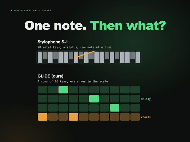
Pocket synth · Cardputer ADVFull disclosure: this one is ours. GLIDE turns the Cardputer ADV's keyboard into four rows that play like strings: notes slide into each other, scale lock (A minor pentatonic by default) means no wrong notes, and holding fn+K lets the mic hear the key of the song in the room.
Get GLIDE ready to play ($119.99)
It arrives on a Cardputer ADV with GLIDE already installed, so you can play first and tinker later. Your LED experiments and GLIDE can share one device. With Launcher installed, press BTN RST (the left trigger on the top edge) and tap a key as it restarts to get to the menu, then pick GLIDE again. You can try GLIDE in your browser right below this guide.
ESP32 LED FAQ
Can I plug an LED filament straight into 5V?
Only if it is sold as a 5V part. A 5V COB filament lights straight from a 5V pin and GND with no resistor or code, and it stays on whenever the board is on. A 3V filament, such as Adafruit nOOds rated at 50 mA, is overdriven on 5V and runs hot, so it needs a resistor or a MOSFET circuit.
Can an ESP32 power an LED directly from a pin?
Yes, a single small LED with a resistor in series. Aim for about 10 mA: for a red LED on a 3.3V pin, a 150 ohm resistor gives about 8.7 mA. Anything hungrier, like an LED filament or a strip, should take its power from 5V and use the pin only to switch it or send data.
What resistor do I need for an LED on an ESP32?
For a red LED at 3.3V, use 150 ohms for about 8.7 mA, 220 ohms for about 6 mA or 330 ohms for about 4 mA. White and blue LEDs need about 3.0 to 3.4V, so they may not light reliably from a 3.3V pin; power them from 5V through a transistor instead.
How many WS2812 LEDs can an ESP32 power?
The ESP32 pin only sends data, with no resistors needed per LED; the LEDs run on 5V, and each can draw up to 60 mA at full white. On a small board's 5V output, such as the Cardputer's Grove port, keep to about 8 to 16 LEDs with FastLED capped at around 300 mA. Longer strips need their own 5V supply with the ground shared with the ESP32.
Do I need a level shifter for NeoPixels on an ESP32?
Adafruit recommends a level shifter such as the 74AHCT125 for 3.3V boards. With a short data wire it often works without one. If the first LED flickers or shows random colours, add the level shifter.
What happened to ledcSetup and ledcAttachPin?
They were removed in Arduino-ESP32 3.0 and merged into ledcAttach(pin, freq, resolution), and ledcWrite now takes the pin instead of a channel. PlatformIO's espressif32 6.x platform still ships core 2.0.17 with the old functions, so a sketch that checks ESP_ARDUINO_VERSION_MAJOR works on both.
Why is my ESP32 OLED screen blank?
Usually the I2C address. Most SSD1306 boards use 0x3C, but Adafruit's 128x64 board uses 0x3D. Run an I2C scanner to see what is connected, and check that SDA and SCL are not swapped. M5Stack's Unit OLED uses an SH1107 controller, so it needs an SH1107 driver rather than an SSD1306 one.
Useful? Pass it on
← Browse all guides